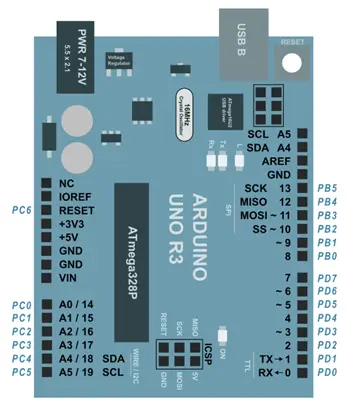
| Digital Pins (0 – 13)(14 – 19) | Digital Pins |
| Analog Pins (A0 – A5) | Analog-to-Digital Pins (Analog Input Pins): Analog inputs are read using a 10-bit analog-to-digital converter (ADC), which converts the analog signal into a digital value ranging from 0 to 1023. Pins A0 – A5: These are the primary analog input pins. Each pin can measure a voltage range of 0 to 5V, and the 10-bit resolution allows for 1024 different values (0–1023). Pins A0 – A5 can also function as digital pins (14 – 19): Apart from their analog input functionality, these pins can be used as additional digital I/O pins, numbered 14 to 19 when configured as digital. |
| PWM pins (3, 5, 6, 9, 10, 11) | PWM Outputs with 8-bit Resolution (0 – 255) |
| Interrupts | Pin2 – Int.0 Pin3 – Int.1 |

No Data Available in this Section
Articles about Arduino
No posts were found.

